The following is a brief overview of each of these applications and systems.

The simulated operator station was a custom developed system for experimental testing to capture the SA of each participant. The appearance and function of this system approximated the look, feel, and interaction of a generic GCS.
 The system hardware was composed of several components that facilitated test participant use of the experimental visual interaction methods (i.e., static eyepoint, analog joystick, head tracker, uninterrupted hat/POV switch, and incremental hat/POV switch). The cost of the system hardware was $875.
Head Tracker/Virtual Joystick Application -
The head tracker/virtual joystick application was designed to run on a Windows XP system, using the DirectX 9.0c, Wiimote, and PPJoy support libraries to accept input from a Nintendo Wii remote device over a bluetooth connection established through the Toshiba bluetooth stack and USB bluetooth adapter. Once the Wii remote was configured for operation and interfaced to the Windows PC, it was able to track the position of an IR LED within the field of view (FOV) of the Wii remote device camera (i.e., head tracker camera). The captured IR LED position was mapped to a two dimensional area (X and Y axes) using the Wiimote library components and translated into a pitch (rotation about head’s Y axis) and yaw (rotation about head’s Z axis) value. The application has several unique features:
- two-dimensional rotational angle calculations (used Pythagorean geometry)
- tuning parameters (factor, response curve, and initial calibration)
 This application was designed to capture and process user inputs for the control of the visual eyepoint and displayed the egocentric visual environment, dynamic depiction of geometric objects, and movement of the visible screen area within the visible environment area. The inputs included the head tracker and joystick. There were two primary components to the visual SA test application, the controls/settings window and the interaction controls. Not all of the controls contained in the GUI were necessary for the experimental testing. Additional controls were necessary for debugging and component evaluation in the application development process.
 The visual SA test application was designed to run on a Windows XP system with a video resolution of 800 x 600, using the DirectX 9.0c support library to accept input from joystick devices or through user interaction with the application GUI. The software application used the DirectX 9.0c library to connect to and read the state of the joystick, including axes position and button depression. The software was designed to run the SA experimental test and the associated alignment and familiarization activities.
Tactile Aural Simulated Kinetics (TASK) Rover and Ground Control Station (GCS)
The predecessor of my Ph.D. research to explore the impact of dynamic eyepoint manipulation originated from development and refinement of an earlier concept to replicate the operating environment of a custom built remotely operated vehicle (ROV). This conceptual research was termed Tactile Aural Simulated Kinetics (TASK). Eventually the lessons learned from the development, implementation, and use of the TASK research formed the basis of the recent research, including:
- Mitigating the effects of spatial disorientation
- Identification of dynamic eyepoint interaction techniques
- Effect of visual interaction on operator SA


TASK GCS - User interface that simulated the “Look, feel and sound” of the remote vehicle operating environment. Provided control instructions and data presentation for the TIGER including visual orientation, aural playback (simulated sound) and vibration simulation.
For additional information regarding the TASK system, click this link.
Teleoperation Development Kit (TDK)
The TDK is a customizable/reconfigurable remote servo control system (hardware and software) that replaces the need to design and build the software/hardware of an unmanned vehicle control layer. TDK provides a control solution to unmanned vehicle developers or remote control (R/C) hobbyists with a control radius requirement of 5 miles or less.

Example platforms include:

- Micro Unmanned Aerial Vehicle (MUAV)
- Small Unmanned Aerial Vehicle (SUAV)
- Unmanned Ground Vehicle (UGV)
- R/C aircraft
- R/C cars, trucks, and tanks
- R/C boats
 The TDK replaces the to need to design and build the software and hardware control layer, providing a user with additional time and resources to focus on the development of the actual vehicle platform.
Use of the TDK system would:
- allow individuals unfamiliar with software or hardware development to create an unmanned research, development, or test platform
- facilitate rapid development of complex vehicle controls that provide higher fidelity/increased capabilities
- provide flexibility through reconfigurable design (reuse for other platforms, activities, or requirements)
- increase the accuracy of first person view (FPV) remote control systems
- increase the fidelity of simulate R/C aircraft controls (i.e., use of actual flight sticks/yolks, throttle controls, pedals, and custom developed user interfaces).
Generic Rotorcraft Flight Dynamics Model (FDM)
This application was developed to create a generic rotocraft FDM for comparative analysis purposes. It uses a USB joystick or on screen (i.e., embedded) flight controls (cyclic, collective, pedals, and three stage throttle/engine control unit (ECU) as user inputs to the model. Available airframes include the AS350 Squirrel, SA330 Puma, AH-64/D, EH101 Merlin, and CH-47 Chinook. However, new configurations/airframes can be added by editing a *.xml data file and adding values for the number of rotors, main rotor diameter, tail rotor diameter, total engine horsepower, maximum operating altitude, and the airframe weight. In addition, sling loads can be added to the model and their characteristics (i.e., weight and cable length) modified during operation. The flight dynamics calculations of the FDM take ground effect region, weights, rotor sizing, engine output, and sling loading into consideration. The following are the outputs of the FDM, available through a shared memory interface:
- Vertical Speed
- Altitude
- Speed
- Rotor Torque
- Airframe Acceleration
- Airframe Velocities
- Airframe Rotations
- Latitude/longitude position

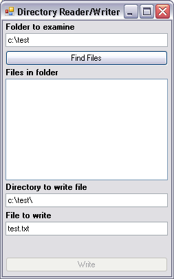
This simple application was developed to provide a search tool to locate specific files or file types in a folder/directory and write the information into a user specified log file (*.txt format).

This application was developed to interface with the FlightGear simulation software using user datagram protocol (UDP). It featured a shared memory interface that could link to the Generic Rotorcraft FDM application to pass through information to use the FlightGear application as an image generator (IG).
On Screen Dialog (OSD)
This application was developed to display a OSD/heads-up-display (HUD) reticle, that is editable by the user. The editable features include (transparency level, color, and ON/OFF state). This application was originally developed to provide an reticle overlay for camera data captured from the operation of an unmanned vehicle (i.e., FPV camera).

No comments:
Post a Comment